HPE 3.65m DB-9 Male to DB-9 Female Shielded Serial Cable HPN: 590976-001,580655-002
- Brand: HPE
- Part #: 590976-001,580655-002
- Specs:-
- :: Type: Server / storage connect cables
- :: Decription: HPE 3.65m DB-9 Male to DB-9 Female Shielded Serial Cable
- :: Length: 3.65 M
- Connectors:-
- :: Supports all standard DB9 serial ports / connectors
- :: Fully shielded
- :: Molded connectors
- :: Thumbscrews
- :: Wires are stright-through
- :: Wire gauge: 28 AWG
- :: Connector A: 1x D-Sub DB-9 RS-232 Serial male
- :: Connector b: 1x D-Sub DB-9 RS-232 Serial female
- :: External / Internal: External
- Condition: New
- Warranty: 1 (one) year Tekmart Africa warranty
-
Key points to note on these 590976-001 HPE DB-9 serial cables:-
These DB9 Cables feature one DB9 male and one DB9 female connector, allowing you to connect a serial device to a 9-pin serial port, or transfer files directly from server-to-server via a serial connection.
The DB9 connector (originally named DE-9) is an analog socket, with 9 pins, from the D-Subminiatures (D-Sub) connector family. The DB9 has the smallest "footprint" of the D-Subminiature connectors. The prefix “D” represents the D-shape of the connector shell.
A null modem DB-9 serial cable (frequently called a crossover cable) is used to connect two Data Terminal Equipment (DTE) devices together without the use of a Data Circuit Equipment (DCE) device in between. For this to work, the transmit (TXD) and receive (RXD) pins on one of the serial connectors are flipped.
These cables are used in the configuring of Intelligent PDUs (as shown below).
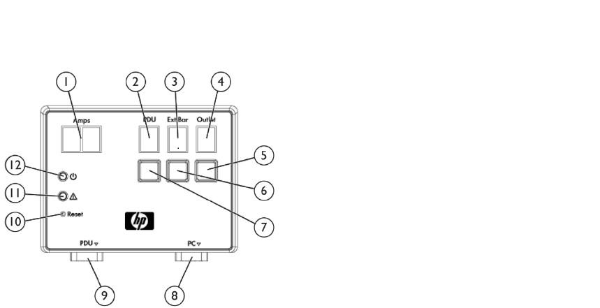
Configuring the Intelligent PDUs (iPDUs) requires several steps.
To configure the initial networking, a serial connection is
used. Using the included DB9-DB9 console cable (P/N 580655-002) connect your serial port to the “PC” (#8) port on the
iPDU management module,
Steps:-
Configure your terminal for 115200 8N1 and press the reset button (#10), the reset button does not impact the PDU itself.
While the controller is rebooting you will be prompted to press a key to enter the Service menu. Once in the Service menu
follow the prompts to set the network information.
• 1. Module Configuration
• 1. Network Configuration
• 1. IPV4 Network Settings
• 1. IPV4 Static Address
- Enter New IP Address: XXX.XXX.XXX.XXX
• 2. IPV4 Static Subnet Mask
- Enter Subnet Mask: 255.255.XXX.XXX
• 3. IPV4 Static Gateway
- Enter New Default Gateway: XXX.XXX.XXX.XXX
• 0. Previous Menu
• 0. Previous Menu
• 2. System Configuration
• 1. Date/Time Configuration
• 1. Network Time Protocol (NTP)
• 1. Primary NTP Server
- Enter Primary NTP Server: XXX.XXX.XXX.XXX
• 2. Secondary NTP Server
- Enter Secondary NTP Server: XXX.XXX.XXX.XXX
• 5. NTP Client
- Enter 1 to enable, 2 to disable (1-2): 1
• 6. Accept Changes
• 0. Previous Menu
• 0. Previous Menu
• 0. Previous Menu
• s. Save New Changes and Restart
Because there is no gateway on the management network, both the IP Address and the default gateway are set to the same
value. Wait for the restart to complete and verify the settings